Every variant of the prototype, drawn to build: three sizes crossed with
four control configurations, then the full engineering plate set. Same airframe logic
throughout — only the highlighted element changes.
Renders
Photoreal concept renders, generated locally on the shop machine — no cloud, no API.
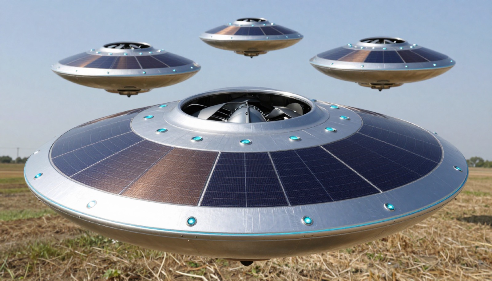
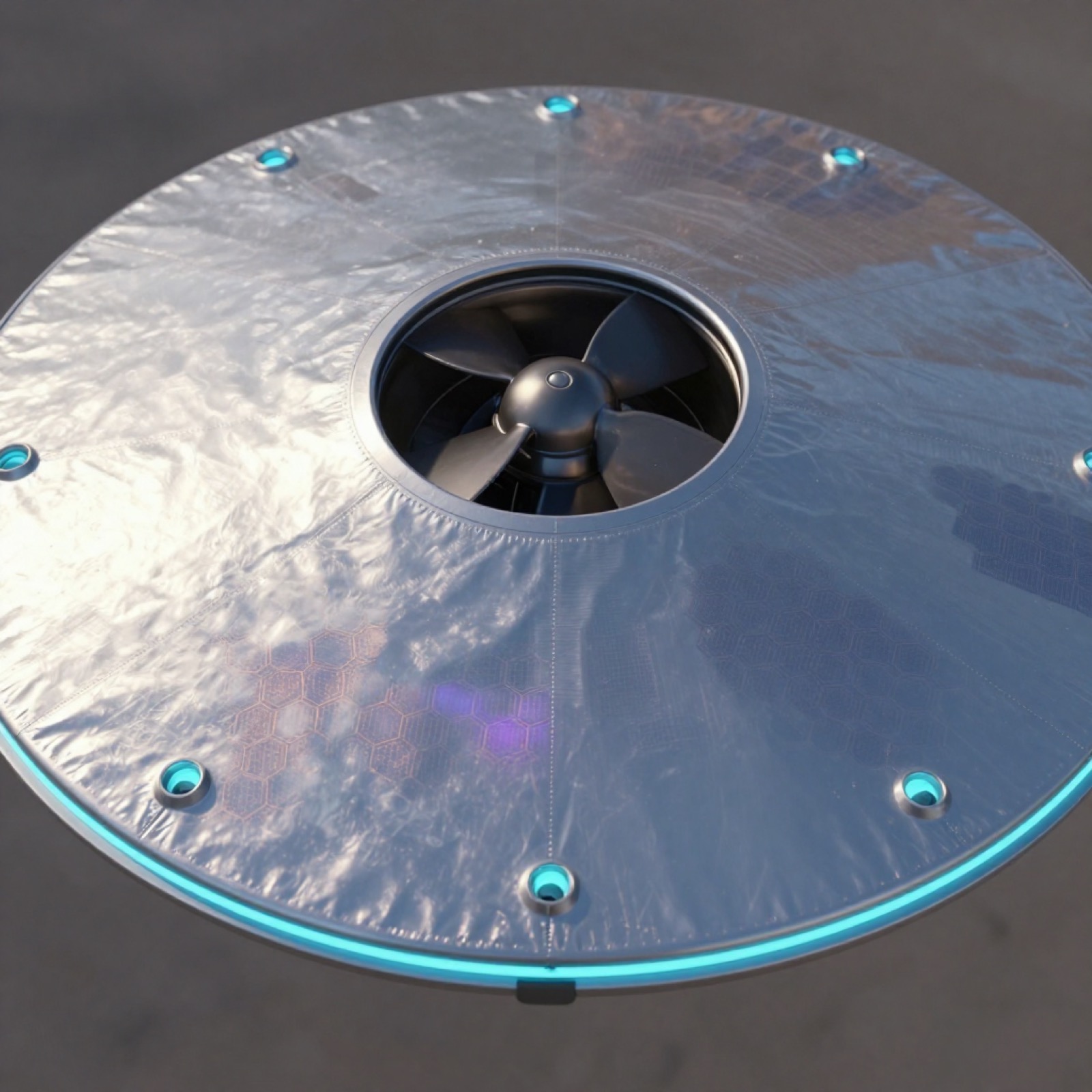
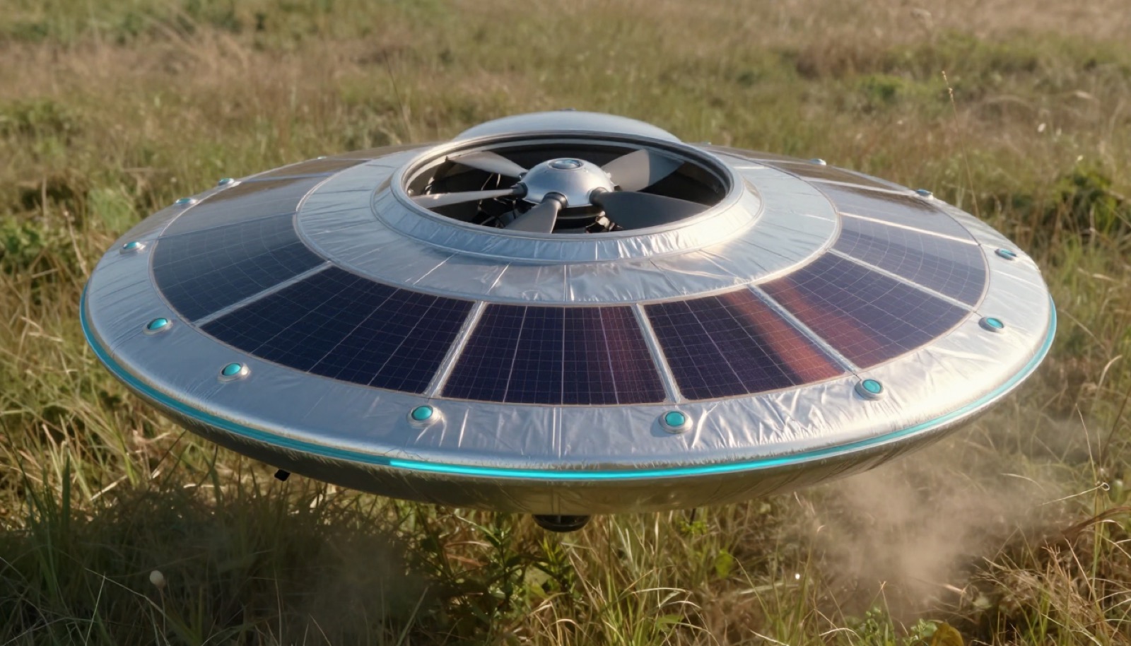
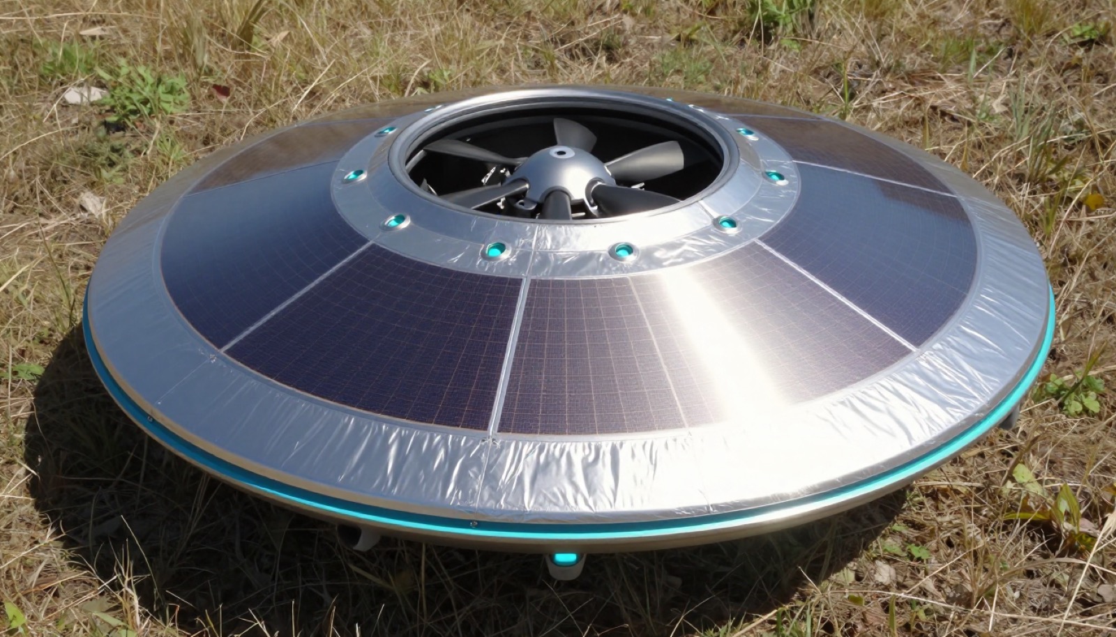
Series 03 — perovskite solar skin, self-recharge concept
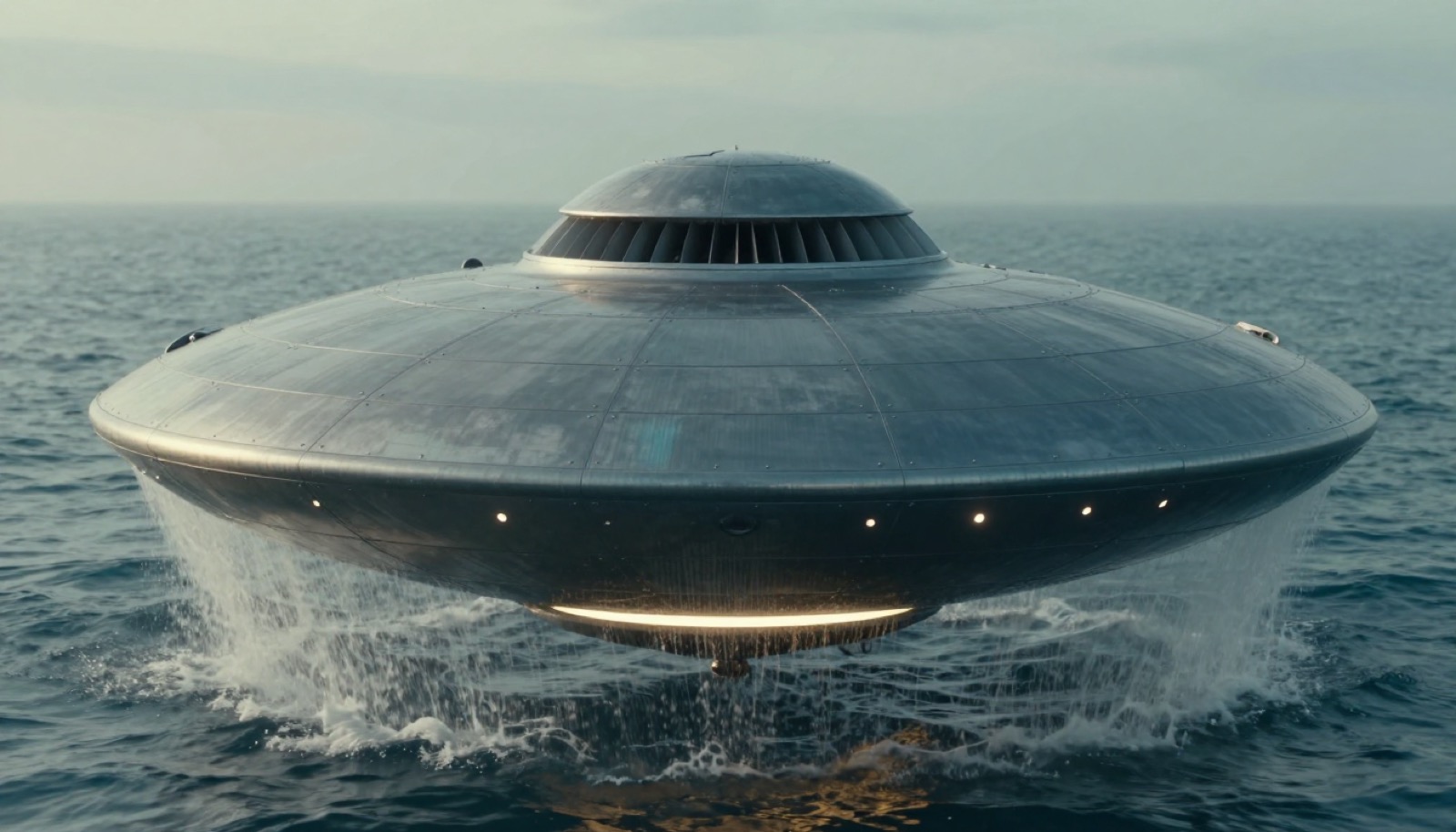
Solar fleet — the self-recharging skin across the sizes.Skin detail — hexagonal perovskite cells under the taut mylar film.Resume mission — lifting off after hours on solar.Solar recharge after an emergency landing — the embedded perovskite grid drinks midday sun.
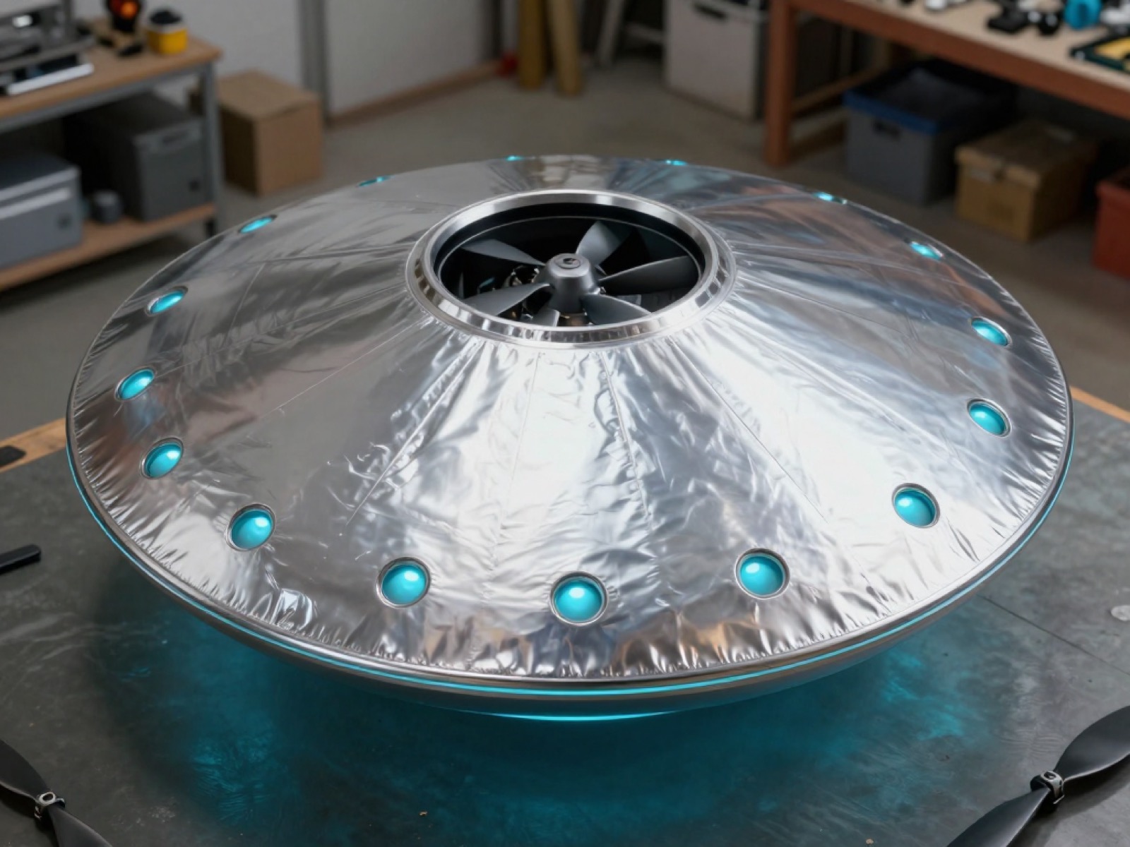
Series 02 — taut mylar skin, to the PD1- schematics
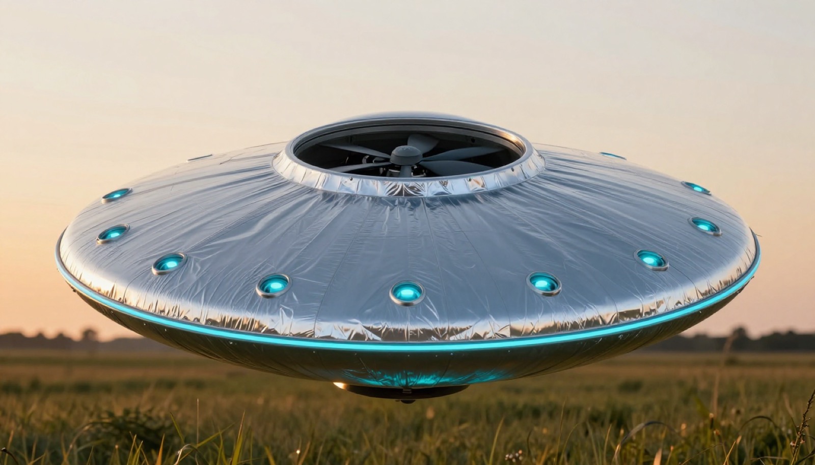
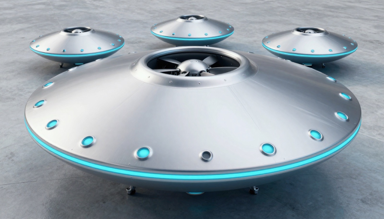
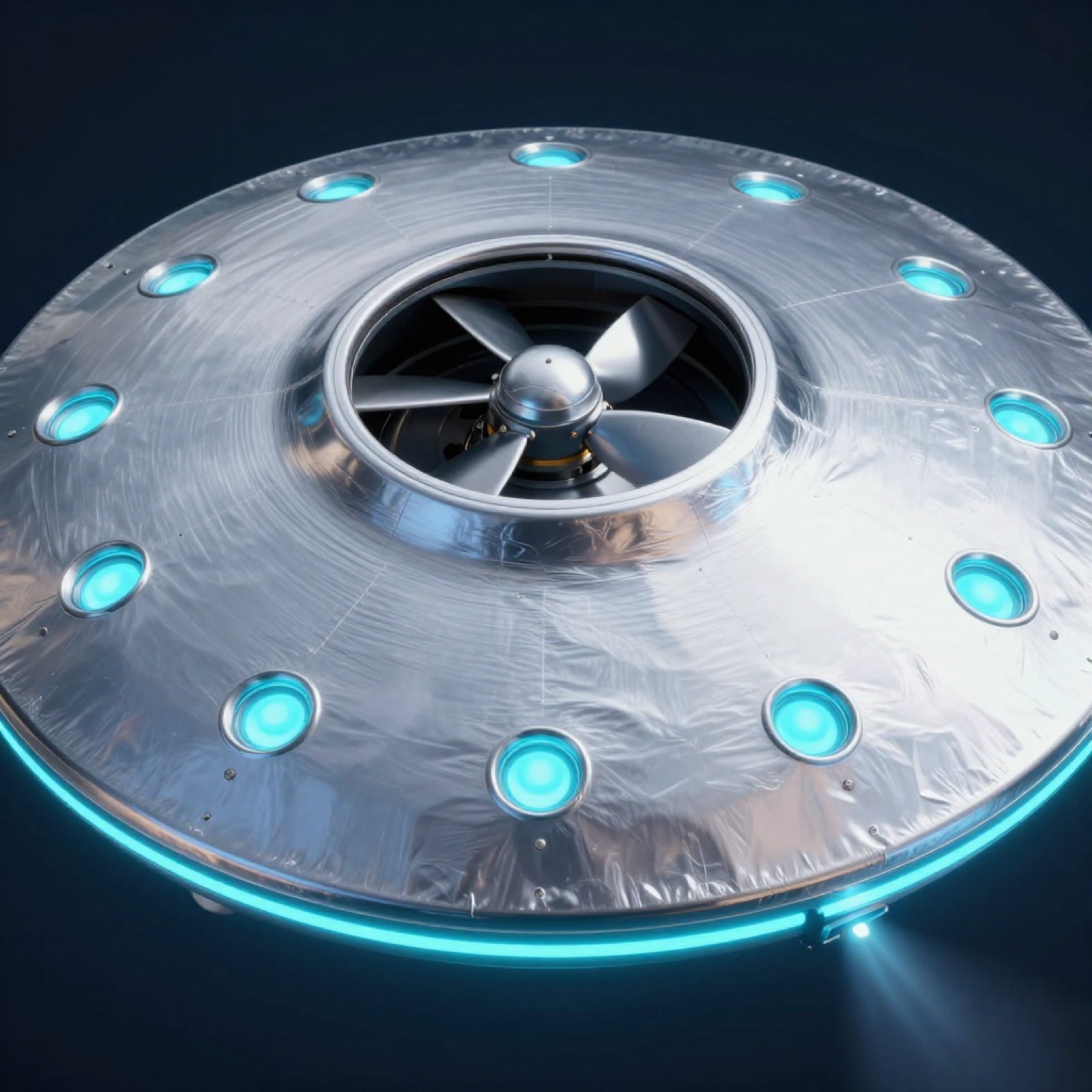
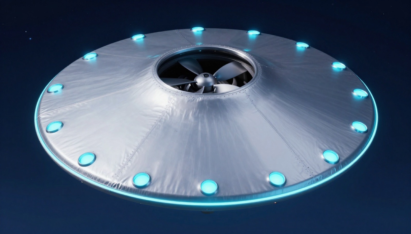
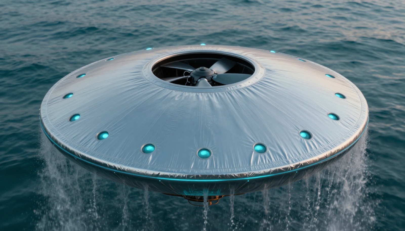
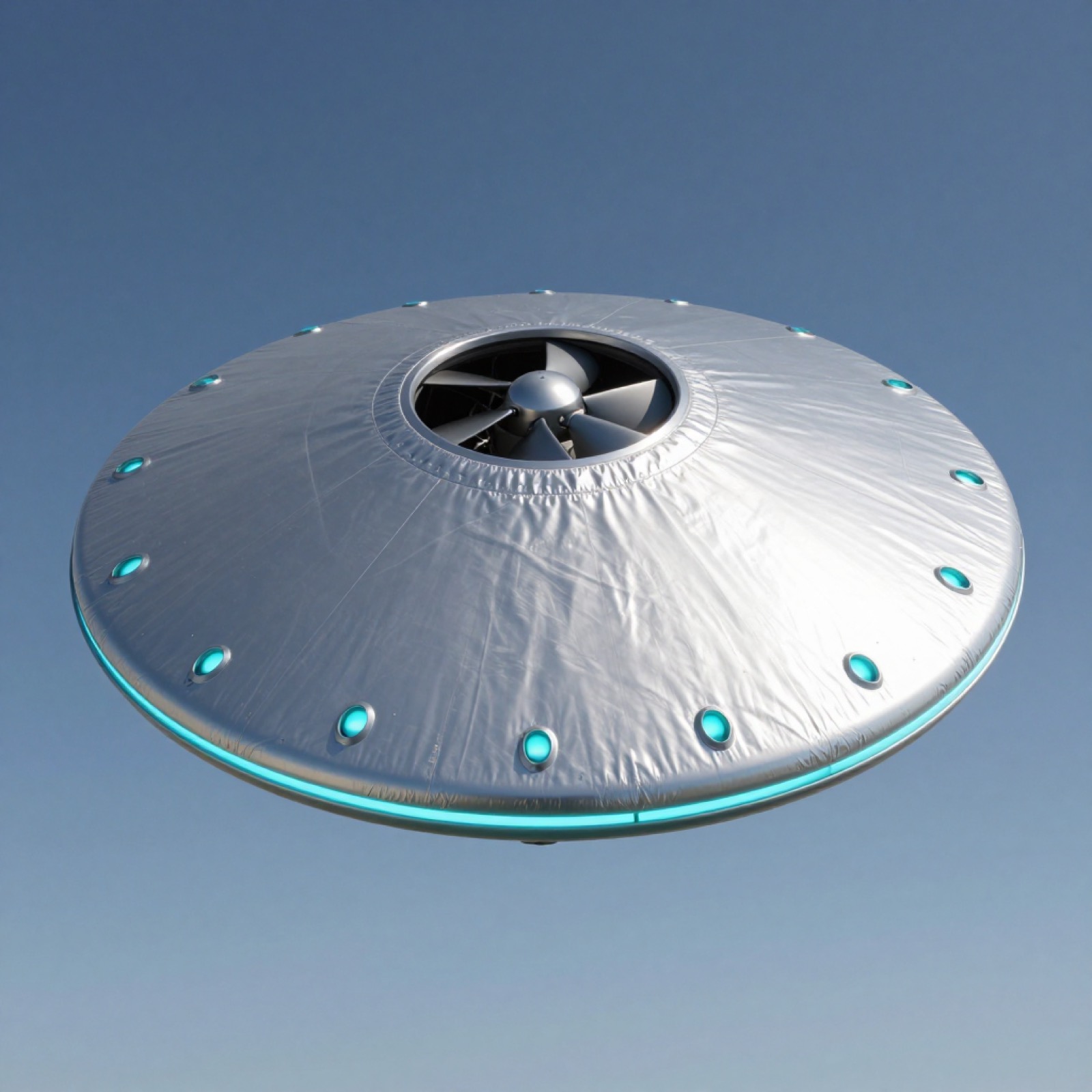
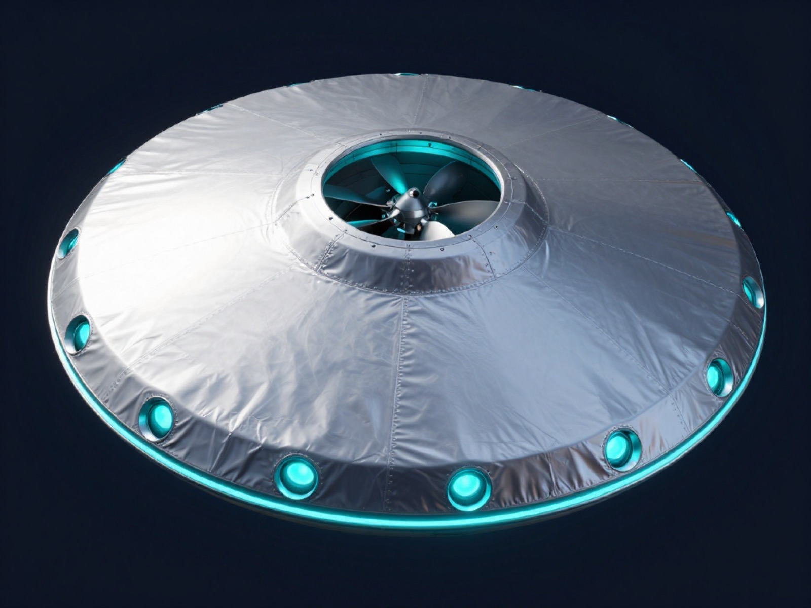
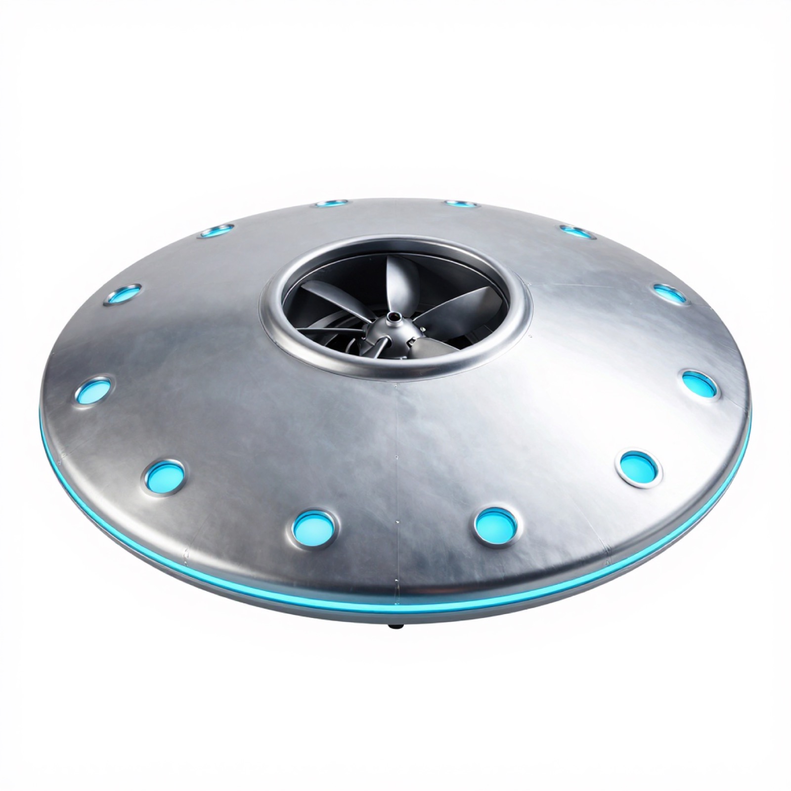
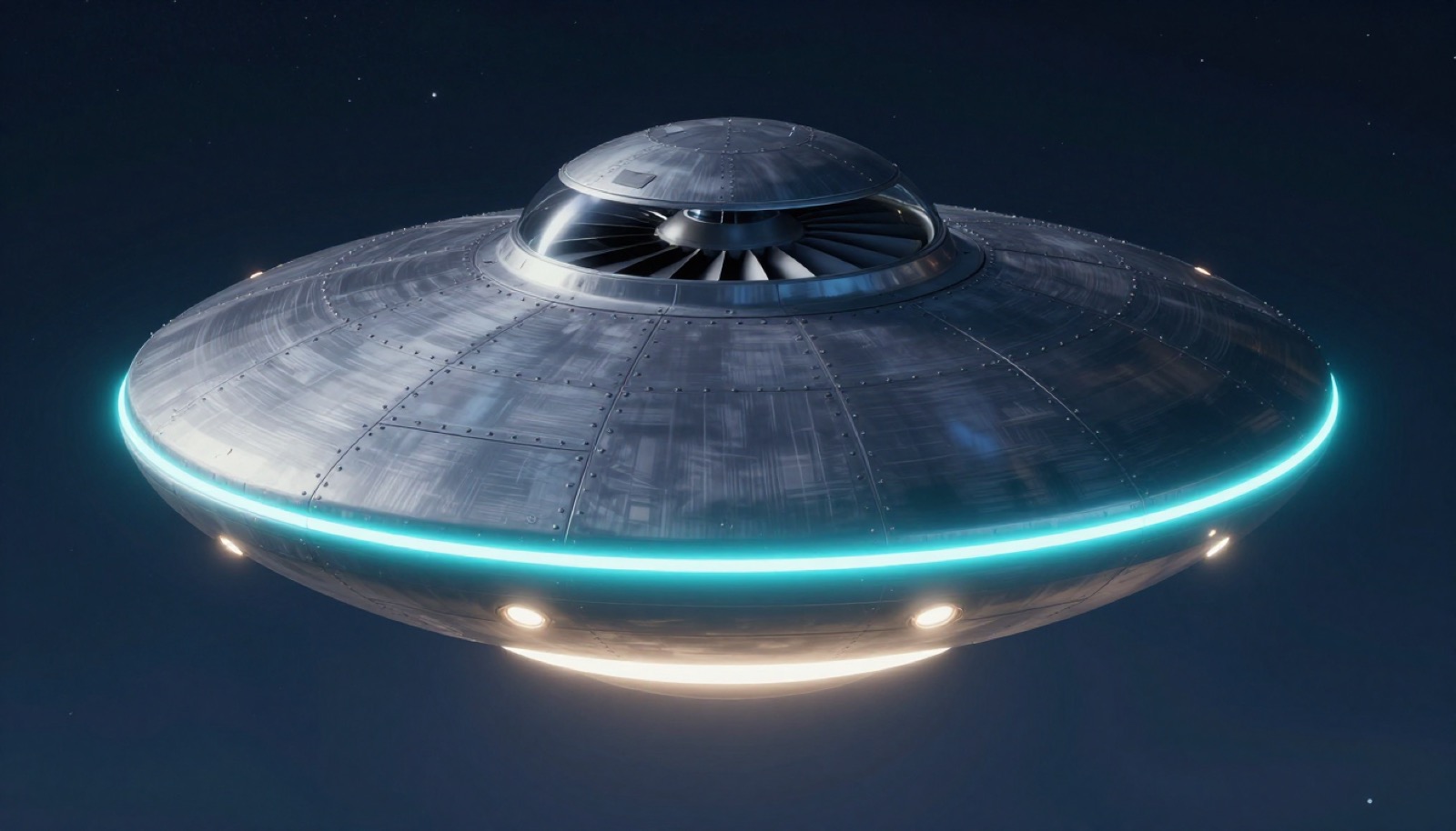
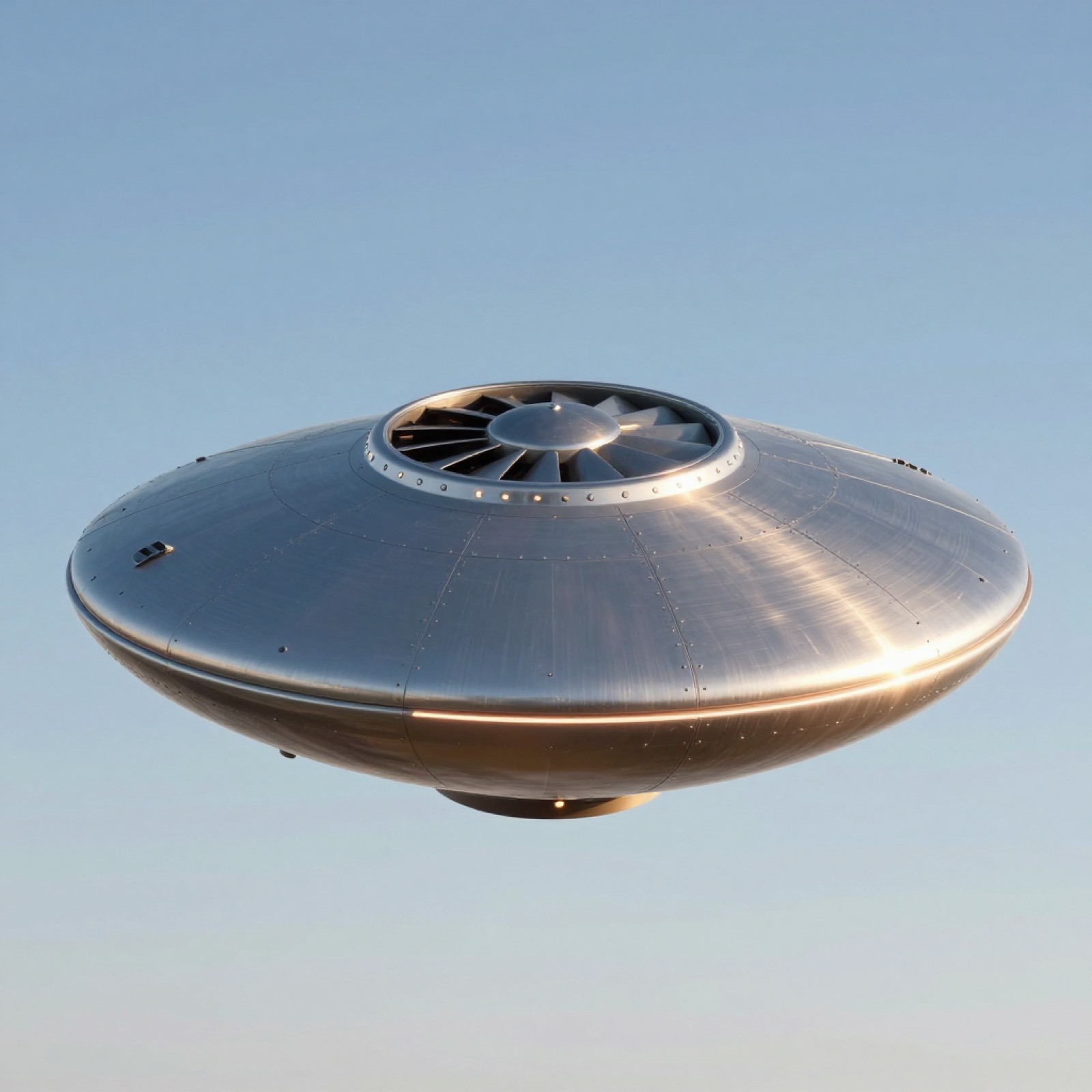
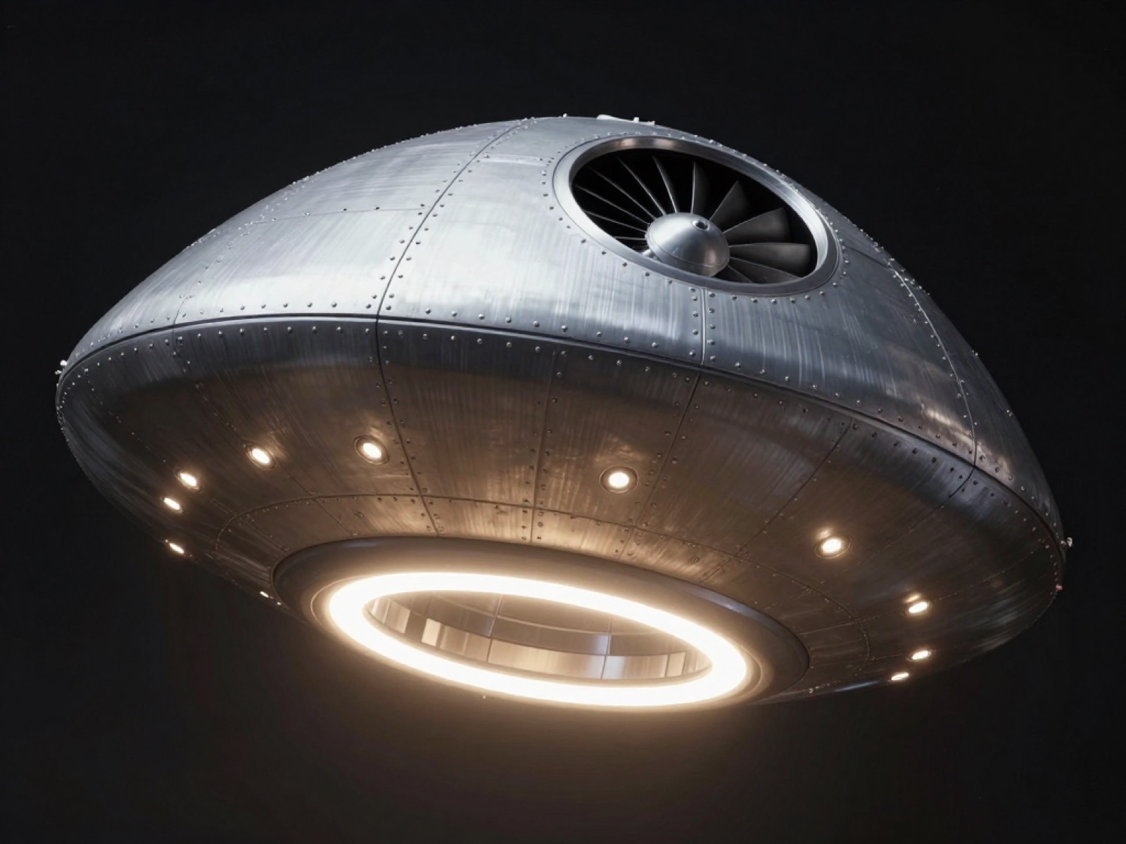
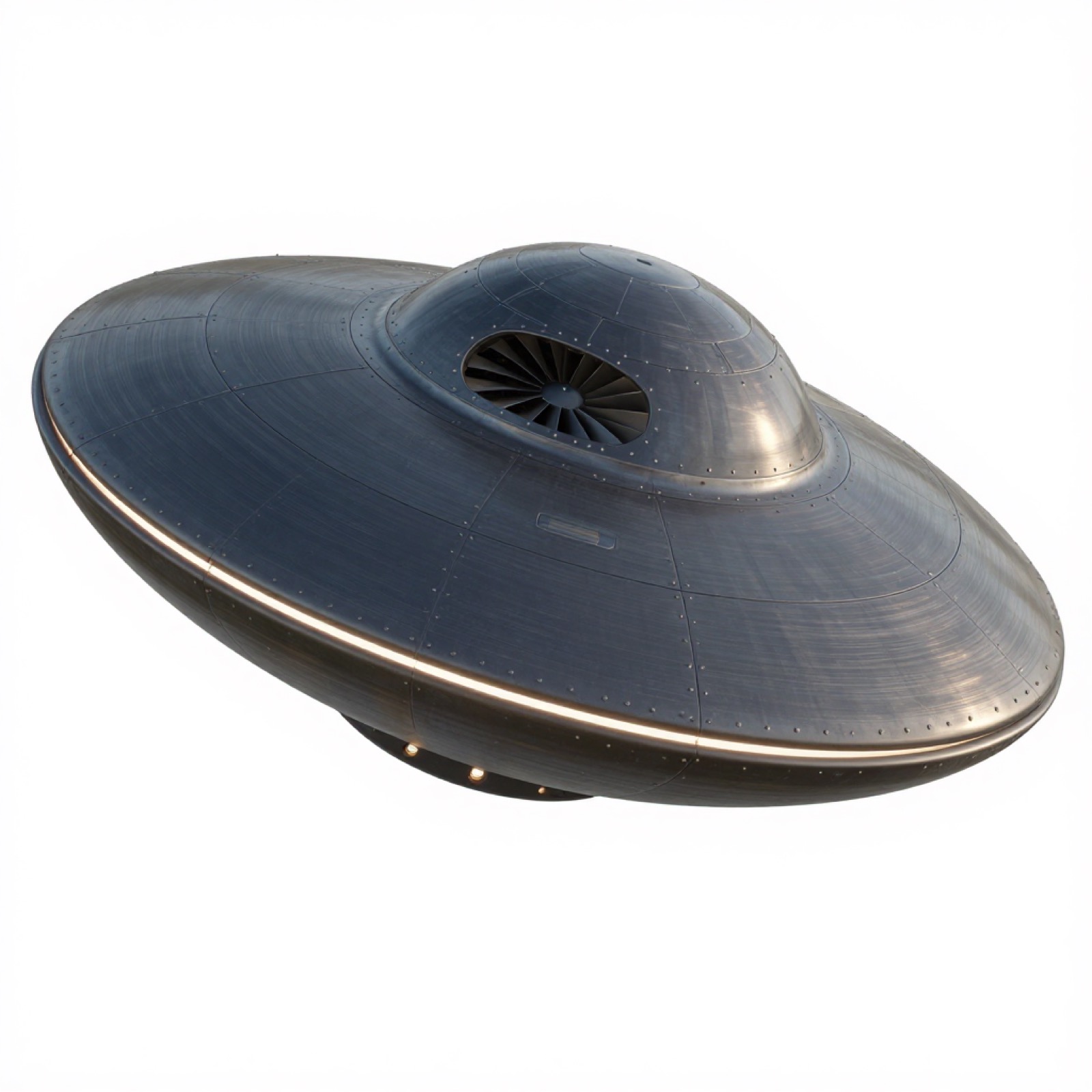
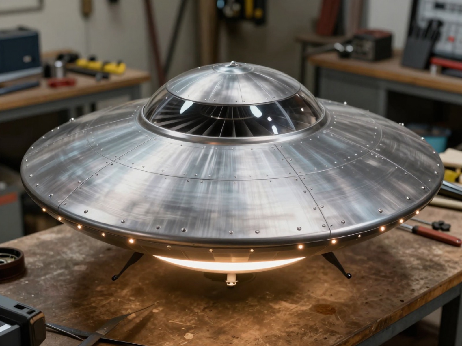
Golden-hour hover over grass.Fleet lineup on the hangar floor.A flush rim port firing a cold-gas burst.Night hover — cyan rim ports and ring.USO: breaking the surface at dawn.PD-1 against open sky — cyan underside ring at power.From below: the 12 recessed cyan ports and the duct outlet.Studio isolation — drum-taut aluminum-doped mylar, seam tape only.On the bench between builds.
Series 01 — first concept study, brushed metal
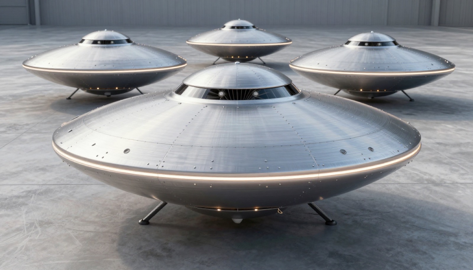
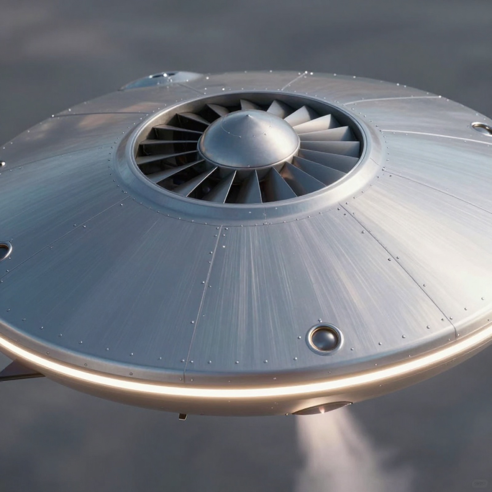
Golden-hour hover over grass.Scout, Baseline and Cruiser on the hangar floor.Macro: a recessed rim port firing.Night hover — cyan rim strip.USO: breaking the surface at dawn.PD-1 against open sky — underside ring at power.From below: recessed ports and the exhaust annulus.Studio isolation — gunmetal hull, panel lines.On the bench between builds.
Variant fleet — 10 permutations
PD1-36 · V-A RINGFLAT. fixed duct — every motion pneumatic — 5.5 kg, 15 in props, He 70 L ≈ 1.3%. first tether article.PD1-48 · V-A RINGFLAT. fixed duct — every motion pneumatic — 7.4 kg, 18 in props, He 170 L ≈ 2.3%. first tether article.PD1-60 · V-A RINGFLAT. fixed duct — every motion pneumatic — 9.5 kg, 24 in props, He 400 L ≈ 4.2%. first tether article.PD1-36 · V-B VECTOR. servo gimbal ±12° vectors the lift — 5.5 kg, 15 in props, He 70 L ≈ 1.3%. baseline · Phases 1–2.PD1-48 · V-B VECTOR. servo gimbal ±12° vectors the lift — 7.4 kg, 18 in props, He 170 L ≈ 2.3%. baseline · Phases 1–2.PD1-60 · V-B VECTOR. servo gimbal ±12° vectors the lift — 9.5 kg, 24 in props, He 400 L ≈ 4.2%. baseline · Phases 1–2.PD1-36 · V-C MAGRING. EM quadrants tilt the stack — no servos — 5.5 kg, 15 in props, He 70 L ≈ 1.3%. Phase-3 R&D.PD1-48 · V-C MAGRING. EM quadrants tilt the stack — no servos — 7.4 kg, 18 in props, He 170 L ≈ 2.3%. Phase-3 R&D.PD1-60 · V-C MAGRING. EM quadrants tilt the stack — no servos — 9.5 kg, 24 in props, He 400 L ≈ 4.2%. Phase-3 R&D.PD1-60 · V-D CRUISER-60. full He annulus · payload hook — 9.5 kg, 24 in props, He 400 L ≈ 4.2%. Phase-3 concept.
Engineering plates
PD1-100 · Top view. Eight rib bays; tank and battery pods oppose each other
across the duct so the center of gravity stays on the rotor axis. Eight down-firing
nozzles (squares) handle pitch/roll and four tangential (arrows) handle yaw —
12 stations on this 48-in baseline, 8 on the 36, 16 on the 60, every port recessed
flush with the skin.
PD1-110 · Side section. The whole duct tilts ±12° on a two-servo gimbal to
vector thrust for forward / back / sideways travel while the body stays level —
the helium annulus and sensors never leave the horizontal plane.
PD1-120 · Bottom view. Downwash exits the central annulus; landing pads sit
outside it so ground effect doesn't tip the craft. The fill port and electronics
hatch are reachable without opening the hull. Every nozzle port is recessed —
nothing protrudes below the skin.
PD1-130 · Exploded view. Six assemblies, all serviceable: the shells lift off,
the He annulus is a drop-in ring, the core chassis carries every heavy component on
the rotor axis, and the valve ring unbolts as one unit with its manifold.
PD1-210 · Gimbal detail. Two nested axes, ±12° each, one 60 kg·cm
HV servo per axis. Hall sensors on the pivots close the loop so the policy knows the
true duct angle, not the commanded one.
PD1-220 · Valve station. One per station — 12 around the 48-in
baseline rim (8 on the 36, 16 on the 60). Each nozzle sits in a recessed well with
its exit flush to the skin: nothing protrudes and the hull stays smooth.
Normally-closed spring return: power loss means the air stays in the tank.
PD1-230 · Duct section. The two numbers that set hover efficiency:
a rounded inlet lip (a ducted rotor gains static thrust from it) and a tight,
constant tip gap — which is why the duct is rigid and the rotors are balanced
before the shell ever goes on.
PD1-400 · Size permutations, drawn to a common scale. Helium only
starts paying rent at 60 in — exactly what the lift-per-liter math predicts. The
recessed rim ring (diamonds) is standard on every size and scales with it:
8 nozzles at 36 in, 12 at 48, 16 at 60. Every size has a job: the Scout's small
payload is still enough to drop a transceiver or locator beacon so the delivery
party can establish comms before the heavy lift arrives; the Baseline flies camera
and training sorties; the Cruiser hauls the cargo that must land alive.
PD1-410 · Configuration permutations. The highlighted element is
what changes; everything drawn in neutral — including the recessed rim control ring
on every model (8 nozzles at 36 in, 12 at 48, 16 at 60) — carries over between
variants.
PD1-420 · Variable-pitch hub & capacitor-discharge landing — Cruiser-60 only.
A Sikorsky-style collective tilts the 24-in blades to chop more or less air at constant RPM.
The failure case is why it earns its mass: the instant the flight computer sees pack voltage
collapsing it flattens the blades into autorotation — the windmilling rotor back-drives the
motors and every remaining watt charges a supercapacitor bank. Baro, GPS and IMU telemetry
time the one discharge that matters: at flare height the cap dumps into the motors as the
collective bites, trading rotor inertia and stored charge for a touchdown at minimum impact
acceleration. Landing policy is payload-first: carrying plasma or rescue gear, the computer
steers the glide to the safest reachable spot even when that is farther from the receiver —
payload survivability outranks delivery proximity. The 36 and 48 stay fixed-pitch — their
rotors don't store enough energy to buy the flare.
PD1-310 · Air path. Working numbers at 120 psi through a 1.5 mm nozzle:
≈1.8 N thrust per station, ≈1.0 N·m of leveling torque at the 24 in lever arm,
≈34 mg of air per 10 ms pulse — roughly 8,000 correction pulses per fill
from the 290 g of air the tank holds.
PD1-320 · Electrical schematic. Solid lines are power, dashed are
signal. The valve rail is fused separately from the lift rail, so a stuck valve can
never brown-out the motors.
PD1-330 · Control stack. One-way trust: the trained policy flies; the Pi
suggests at 50 Hz; the ground LLM only ever tunes and reviews. If every link drops,
the flight controller alone can land it.